Barrel Transfer Gauge
 Barrel Transfer Gauge.
The construction of a barrel arbor is a little more tricky than it initially appears. The dimensions are nominally defined, but the actual dimensions depend on what you've already built.
One such dimension is the inside "cap to cap" dimension. To be sure that the arbor will fit with the appropriate end shake, this dimension needs to be taken directly from the barrel itself. But how can it be measured with the caps in place?
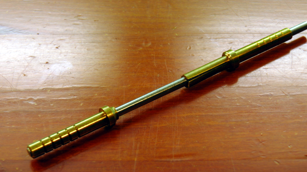
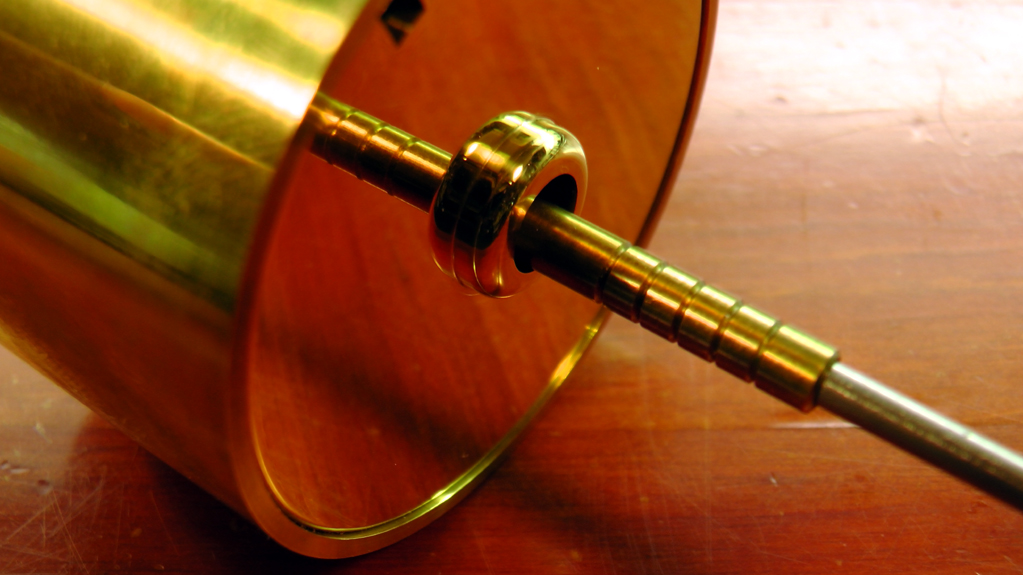
Well fortunately master clockmaker Bill Smith solved the problem with a simple little gauge idea. It consists of 2 shouldered fittings sliding on piece of rod.
One such dimension is the inside "cap to cap" dimension. To be sure that the arbor will fit with the appropriate end shake, this dimension needs to be taken directly from the barrel itself. But how can it be measured with the caps in place?
Well fortunately master clockmaker Bill Smith solved the problem with a simple little gauge idea. It consists of 2 shouldered fittings sliding on piece of rod.
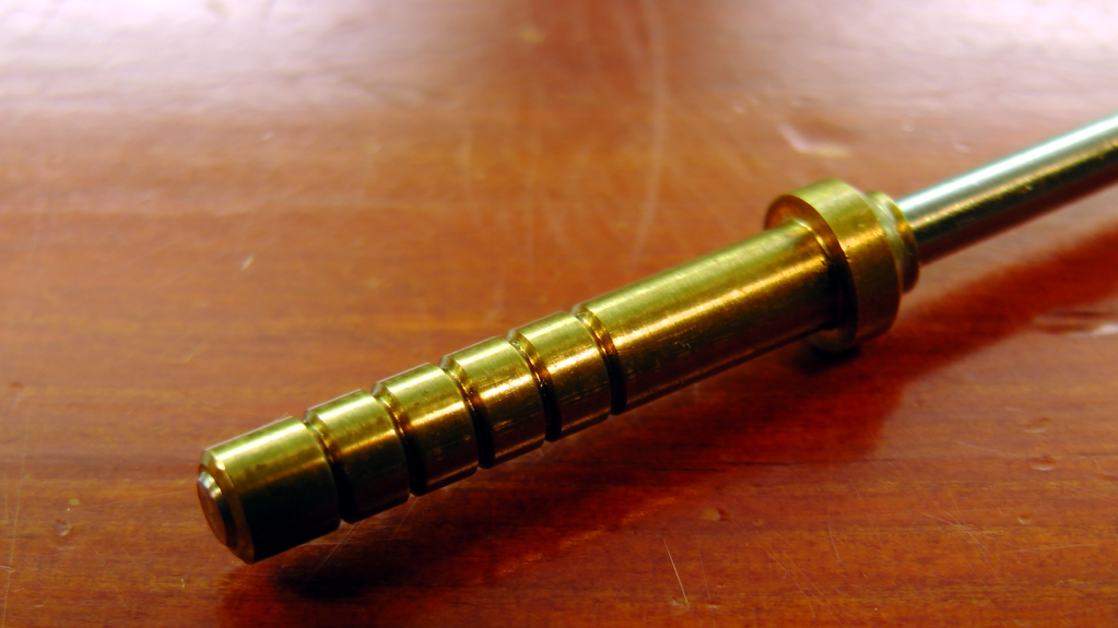
This shouldered fitting is fixed
|
The split end is pushed in, and it gives the necessary friction for the sliding shoulder to hold its position.
|

This shouldered fitting slides as required.
|
The end cap is fitted to the barrel, with the spring absent. The gauge is then inserted into the barrel arbor hole, and the far shoulder of the tool is secured against the far cap wall. The near side shoulder is similarly located against that near side cap wall, by sliding the moveable shoulder. The tool is then carefully removed without disturbing the reading, and the distance is recorded with a digital caliper.
The tool was a nice little lathe project, and performs a key role in the fabrication of a clock.
Designed by WR (Bill) Smith, as detailed in his book "How To Make A Grasshopper Skeleton Clock" pg 17.
The tool was a nice little lathe project, and performs a key role in the fabrication of a clock.
Designed by WR (Bill) Smith, as detailed in his book "How To Make A Grasshopper Skeleton Clock" pg 17.

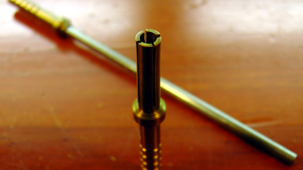
Insert the tool into the barrel
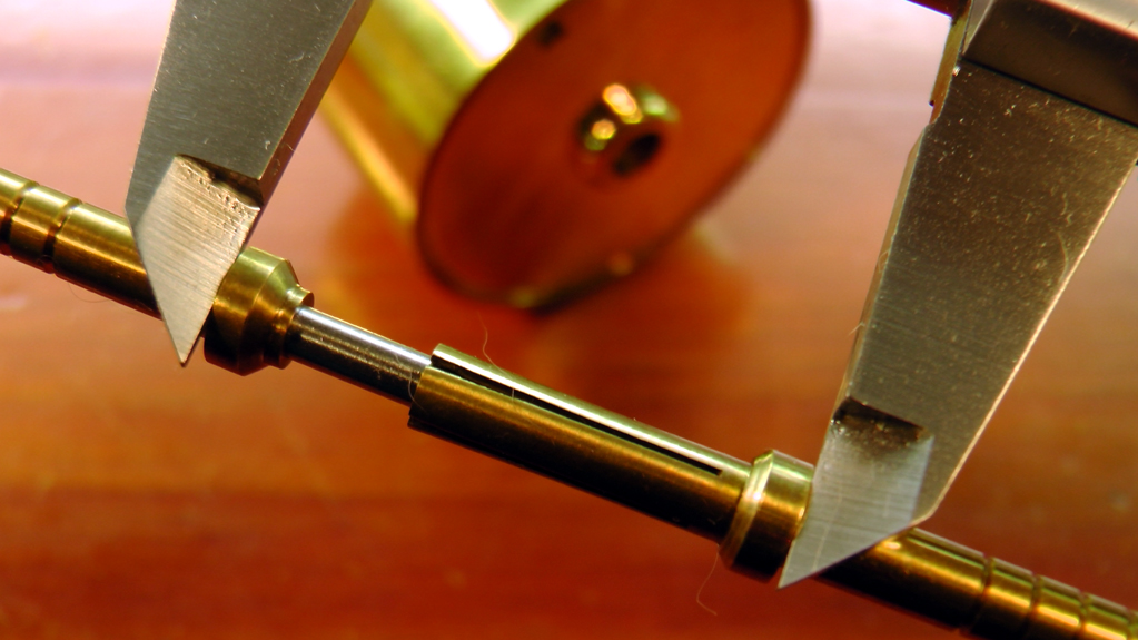
Then read with a caliper
|
Then slide the shouldered fittings apart until they are snug against the inside cap walls.
|

Picking off the cap to cap dimension
|
